


Spline shaft manufacturing from drawings
Custom Spline Shaft Manufacturing
Jinhua Machinery is a custom spline shaft manufacturer in Changshu, China, producing drawing-to-specification components for steering, transmission, pump and industrial drive programs. The review covers internal or external spline geometry, the governing standard or complete tooth data, fit and centering method, mating interface, material, datum relationships, specified treatment requirements, journal finishing and inspection. Verified records support spline rolling for suitable external forms, together with CNC turning, milling and selected grinding processes. Annual volume, tooling, gauges, PPAP or reporting requirements and delivery targets are reviewed before a production route is quoted.
Request a Quote
Direct answer
Verified records support spline rolling for suitable external spline forms and CNC machining or selected grinding for applicable shaft features. Internal spline geometry and other spline-production routes are reviewed from the drawing without assuming a universal in-house method. Spline accuracy is not represented by one grade: each quotation evaluates the governing standard, fit, centering method, mating condition, datums, gauges or analytical reports, treatment requirements and annual volume.
- Technical content reviewed by
- Process Engineering and Quality Engineering
- Last reviewed
- Capability basis
- Production records and internal inspection data
What Is a Spline Shaft?
A spline shaft is a rotating or sliding shaft with teeth or ridges that engage a matching internal spline. Unlike a single key, the spline distributes torque across several teeth. This can improve load sharing, preserve angular position, and create a compact connection between a shaft and a hub, gear, coupling, yoke, steering component, or other mating part.
Spline shafts are not one universal product. A drawing may specify an external or internal spline, involute or straight-sided teeth, a serration, a fixed connection, or a sliding connection. The design can center on the tooth flanks, major diameter, or minor diameter. Tooth count, module or diametral pitch, pressure angle, fit class, lead, profile, effective length, and datum system all affect assembly and torque transfer.
For sourcing, the category should be treated as a made-to-drawing component rather than a catalogue shaft. Jinhua Machinery reviews the complete part, including the spline, bearing seats, journals, shoulders, grooves, threads, holes, flats, sealing areas, and relationships between those features. Buyers can also review the wider custom shaft manufacturing capability.
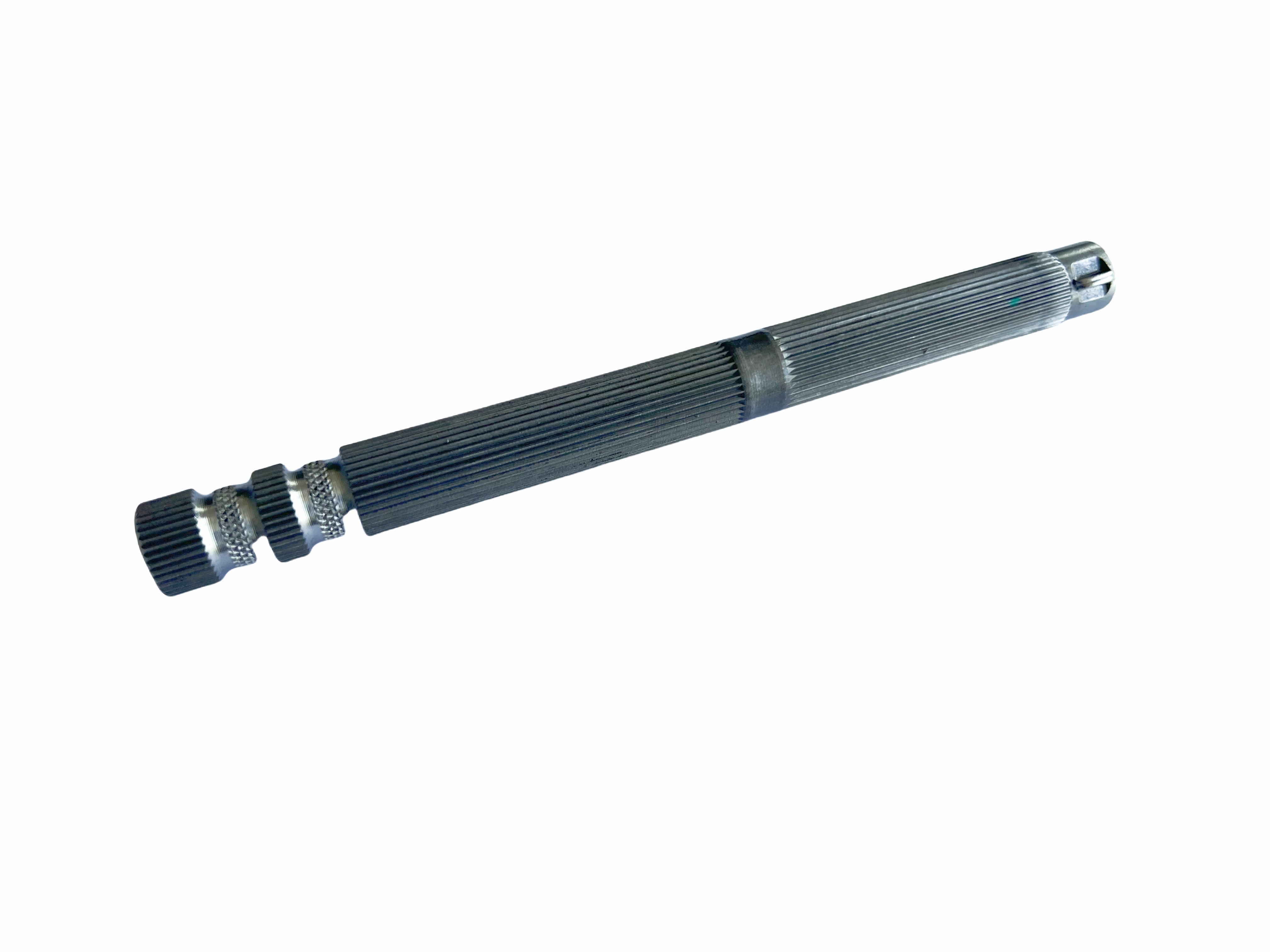
Spline Shaft Manufacturing
Manufacturing begins with the drawing and mating-interface review. The supplier needs to know which surfaces establish functional datums, how the spline is centered, whether the connection slides or remains fixed, and which characteristics govern torque transfer. Material condition, blank type, volume, heat-treatment distortion, finishing allowance, and inspection method are considered before a process is chosen.
Jinhua Machinery's verified records support CNC turning and milling for shaft geometry and spline rolling for suitable external spline forms, subject to material, reduction, geometry, tooling, fit and annual-volume review. Cylindrical, internal and centerless grinding can support selected functional surfaces within their stated ranges. Spline hobbing, shaping, broaching, cold forming and other industry routes are evaluated only when their actual provider boundary and project evidence are confirmed.
Sequence matters because spline generation, specified heat treatment, and final grinding can change datum relationships. Planning may include material preparation, rough turning, the approved spline process, special-process coordination, straightening where permitted, finish machining, deburring, protection, marking and final inspection. The released drawing determines the route.
Before comparing quotations, define whether delivery covers the external spline shaft only, a matching internal-spline component, or an assembled connection. Identify the released drawing revision, governing spline standard, centering and fit definition, and any customer-supplied mating part or functional gauge. A shaft-only quotation should not silently include validation of an unspecified mating component.
Compare tooling and gauge responsibility, the approved spline-generation route, heat treatment and final finishing, inspection records, marking and protection on the same basis. Confirm any external operation and the records supplied with it before ordering. An agreed report package and delivery condition belong in the quotation, rather than being assumed from a sample photograph.
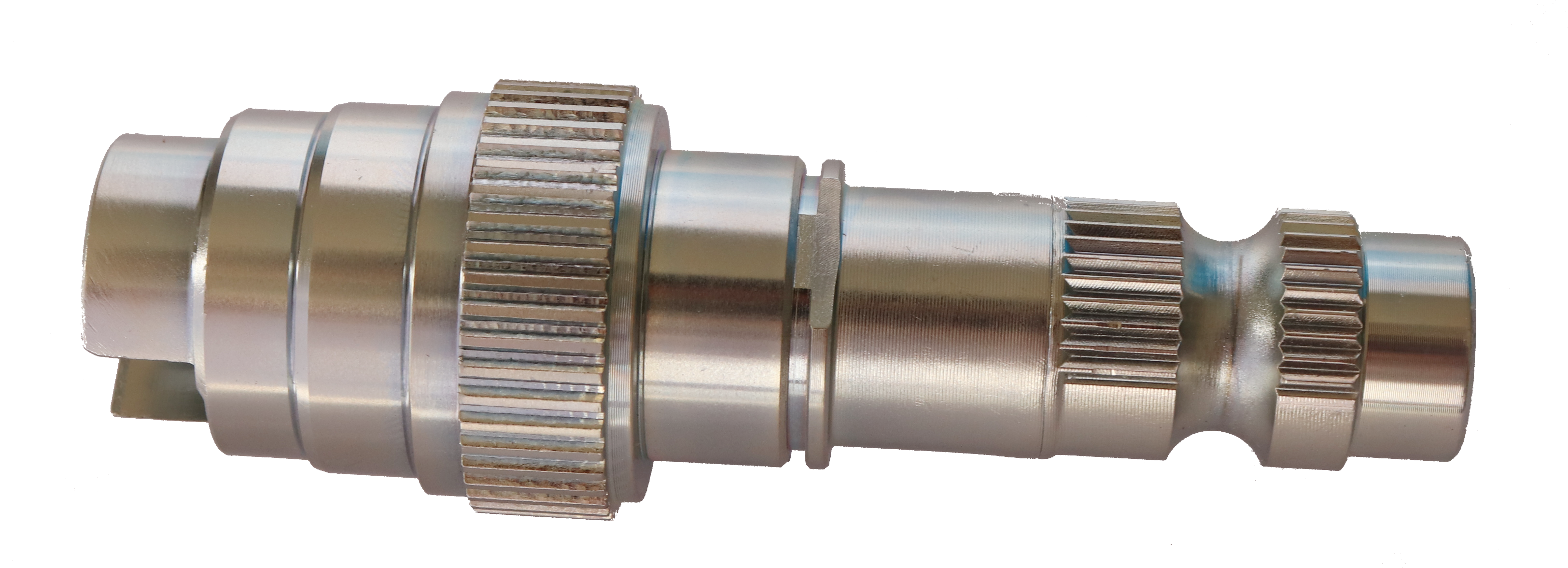
Spline Shaft Materials
Material selection balances torque, fatigue, impact, wear, size, weight, corrosion exposure, heat treatment, machinability, and cost. Common carbon-steel choices for moderate spline-shaft duties include Chinese 35 and 45 and SAE 1035 or 1045. Higher hardenability and fatigue requirements may lead to 40Cr, 42CrMo/SAE 4140, or SAE 4340, depending on section size, core properties, and heat-treatment route.
Where a hard case and tough core are needed, commonly specified case-hardening families include 16MnCr5, 20MnCr5, 20CrMnTi, and SAE 8620. Corrosion-sensitive designs may consider 303, 304, or 316 stainless steel for moderate loads, or 410, 420, and 17-4PH where higher hardness or strength is required. Aluminum grades such as 6061 or 7075 and engineering polymers may suit lightweight or lower-duty spline systems only when the design validates their wear, stiffness, temperature, and mating behavior.
The RFQ should state exact grade, standard, delivery condition, mechanical properties, cleanliness, and permitted substitutions. For a sliding spline, material and surface pairing must address wear, fretting, lubrication, contamination, and relative hardness. For a fixed spline, torque reversal, assembly fit, and fatigue near the runout can dominate. Material, geometry, heat treatment, and finish require one coordinated review.
Spline Shaft Heat Treatment
Heat treatment is commonly used to create a wear-resistant spline surface while retaining core strength and toughness. Carburizing is often considered for low-carbon alloy steels when a hard case and tough core are required. Induction hardening can selectively harden spline teeth or journals on suitable medium-carbon steels. Quench and temper can establish through-section properties before machining or local hardening. Nitriding may be specified where the alloy, case requirement, and distortion target make it appropriate.
The drawing should define more than a process name: hardness scale and range, test location, effective or total case depth, areas to harden or protect, allowable decarburization, microstructure criteria, straightness, and post-treatment finishing. Distortion planning is particularly important for long shafts, thin walls, internal splines, and parts with multiple datum journals. Rough-machining allowance, spline timing, fixtures, straightening limits, and grinding stock should be considered together. Certificates or hardness traverses should be identified during quotation when required.
Spline Shaft Tolerance
Spline tolerance is a functional system, not only tooth thickness. A drawing may control profile, lead, pitch variation, accumulated pitch, runout, major and minor diameters, effective fit, actual fit, and the relationship between the spline and bearing journals. It should identify the governing spline standard or provide complete geometry for a proprietary form. Sliding assemblies may prioritize backlash and movement; fixed assemblies may prioritize contact distribution, torque capacity, and assembly method.
Inspection can use functional gauges, analytical gear measurement, span measurement, measurement over pins or balls, diameter instruments, roundness equipment, roughness instruments, and runout checks referenced to drawing datums. A functional gauge confirms assembly condition but may not identify the individual tooth characteristic causing a failure. Analytical measurement provides more detail but requires an agreed definition and report format.
Bearing-seat diameter, concentricity, total indicated runout, straightness, shoulder position, thread alignment, bore size, seal-surface roughness, and spline-to-journal relationships can determine performance. Mark critical characteristics and state sampling, reports, material certificates, heat-treatment records, traceability, and gauge responsibility. Numerical limits must come from the released drawing and the functional mating condition. See the quality inspection approach.
Spline Shaft Applications
Spline shafts are commonly used where a compact interface must transfer torque while maintaining angular location or allowing axial movement. Automotive steering columns and assist systems use splined connections to transmit driver or actuator torque. Gearboxes and reducers use them between shafts, gears, couplings, clutches, and hubs. Pumps, electric motors, construction machinery, motorcycles, e-bikes, bicycles, and industrial motion-control equipment can use spline shafts where repeatable assembly and engagement are required.
The application changes the priorities. Steering systems can emphasize backlash, fit, corrosion protection, marking, and traceability. Transmission components can emphasize fatigue, tooth contact, case hardness, runout, and bearing relationships. Sliding couplings may prioritize flank finish, lubrication, wear, and axial freedom. Motor or pump assemblies may prioritize concentricity, seal surfaces, noise, and balance.
Jinhua Machinery supports drawing-based assessment rather than selecting the spline design for the customer. Engineering responsibility and final application validation remain with the design owner unless otherwise agreed. Use the spline shaft quotation enquiry to describe the application and required supply scope; send controlled drawings as email attachments after the initial enquiry.
Spline Shaft FAQ
What information is required to quote a custom spline shaft?
Start with the controlled drawing revision and any available 3D model. Add the spline standard or complete tooth data, fit and centering method, shaft datums, exact material and treatment requirements, mating-interface information, quantities and delivery condition. State whether a functional gauge, mating part and inspection report are supplied, requested or outside the order.
What is the difference between an involute spline and a straight-sided spline?
An involute spline uses an involute tooth form and commonly centers on flanks or diameters, while a straight-sided spline uses parallel tooth sides. The correct choice depends on the assembly design, load, space, manufacturing route, and drawing standard.
Which heat treatment is commonly specified for spline shafts?
Carburizing, induction hardening, quench and temper, and nitriding are commonly considered, but they produce different case depth, core strength, distortion, and finishing needs. The drawing must define the required result.
What precision is available for spline shafts?
Reviewed spline shafts can use the verified ground-diameter and precision-bore capabilities stated on this page. Spline accuracy is not reduced to one universal grade: Jinhua Machinery evaluates the customer-specified standard, fit, centering method, gauges, analytical measurements, datum relationships, and reporting requirements.
How should spline shaft quotations be compared?
Compare the same spline definition, supply scope and delivery condition. Check who supplies or approves tooling and functional gauges, which machining and external processes are included, and which records accompany the shaft. A prototype route or a sample that assembles does not by itself establish the approved repeat-production route.
Related Manufacturing Cases
These are specific made-to-drawing examples. Their materials, processes and tolerances are component-specific and do not define a universal catalogue specification.


Request a quote
Request a Quote
Send drawings. Get a custom spline shaft manufacturing review.
Send the drawing and revision, material, critical dimensions and tolerances, surface and heat-treatment requirements, annual usage, batch volume, inspection or PPAP documents, packaging and delivery target.