


Helical Gear Manufacturing
Jinhua Machinery manufactures helical gear shafts, helical gear wheels, and machined drive components for gearbox, reducer, steering, motor, and industrial machinery programs.
Request a Quote
Jinhua Machinery is a custom helical gear manufacturer in China supporting drawing-based gear wheels and integrated gear shafts for automotive and industrial OEM programs. The quotation review connects module or DP, pressure-angle convention, helix angle and hand, tooth count, face width, modifications, material, treatment specification, functional datums, mating gear, and inspection records. Documented in-house work includes CNC turning, milling, gear hobbing, gear grinding, external grinding, and dimensional or gear inspection within published ranges. For reviewed heat-treated and ground cylindrical gears, published capability reaches ISO 1328-1 / GB/T 10095 Grade 7 within module 4, tip diameter 200 mm, and face width 50 mm, with tooth surface Ra 0.8 μm, subject to drawing review. Gear shaping is evaluated only after drawing review, and standards are not treated as directly equivalent.
Direct answer
Jinhua Machinery manufactures helical gears and helical gear shafts from customer drawings for gearbox, reducer, steering, motor and machinery programs. Planning covers normal or transverse tooth definitions, helix hand and angle, material, blank route, heat treatment, grinding allowance, bore or journal datums and inspection reporting. Reviewed cylindrical helical gears can achieve ISO 1328-1 or GB/T 10095 Grade 7 and Ra 0.8 μm tooth-surface roughness within the published range, subject to drawing review.
- Technical content reviewed by
- Process Engineering and Quality Engineering
- Last reviewed
- Capability basis
- Production records and internal inspection data
What Is a Helical Gear?
A helical gear has teeth cut at an angle to the axis. Engagement begins gradually across the face width, so multiple teeth can share load and the mesh can operate more smoothly than a comparable straight-tooth gear. Helix angle and hand create axial thrust, which must be supported by bearings and the housing.
External and internal helical gears, helical gear shafts, and crossed-helical arrangements serve different geometries. The drawing normally defines module or DP, normal or transverse pressure angle, helix angle, hand, tooth count, face width, profile and lead modifications, quality grade, backlash, and datums. Mating gear data is needed to interpret those values correctly.
Jinhua Machinery supports drawing-based helical gears and gear shafts for automotive, new energy vehicle, reducer, steering, motor, gearbox, and machinery programs. The manufacturer reviews production feasibility, while the customer retains gear-design and application responsibility.
Helical gears used on parallel shafts normally mate with opposite hands, while crossed-helical arrangements follow different geometry and load assumptions. Double-helical or herringbone forms can oppose axial forces but add manufacturing and assembly complexity. A category name alone does not distinguish these cases, so shaft arrangement and mating-member data should be part of the controlled specification.
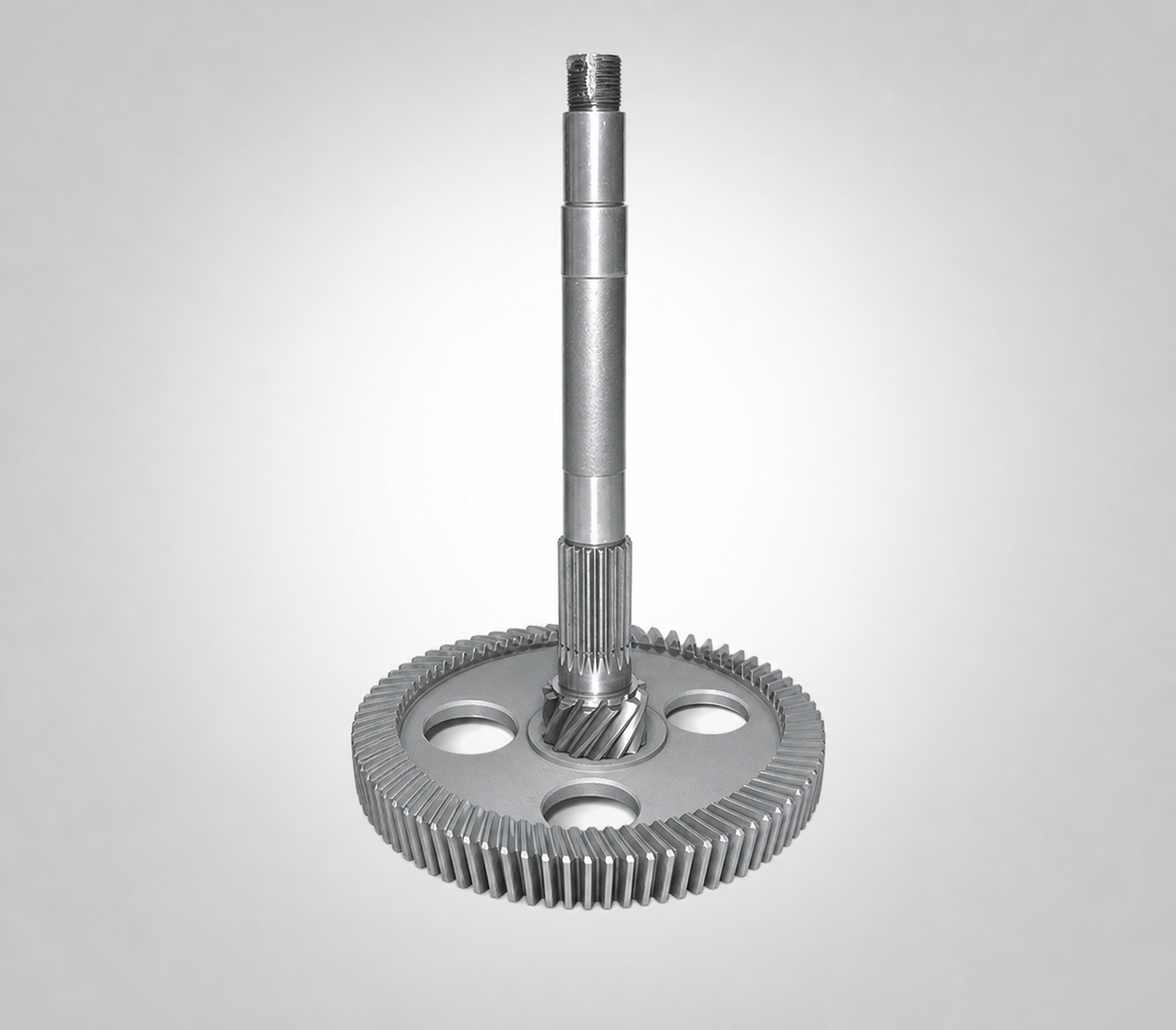
Helical Gear Manufacturing
Review links the tooth definition to blank, bore, hub, shaft, spline, keyway, shoulder, and bearing features. Material, heat treatment, annual demand, inspection standard, and finishing determine the documented hobbing or grinding route, while gear shaping, honing, or another process is evaluated only after drawing review.
A common sequence may include blank preparation or forging, rough turning, bore and face machining, gear cutting, deburring, heat treatment, datum recovery, gear and diameter finishing, cleaning, protection, and inspection. Gear shafts require special attention to tooth-to-journal concentricity. Internal teeth or interrupted features can limit tool access.
Heat-treatment distortion can alter helix lead, profile, pitch, and runout. Cutting corrections, grinding allowance, fixturing, and final inspection should be planned before production. Repeated programs may justify dedicated cutters, fixtures, gauges, or automated handling, while prototypes may use flexible machining.
For a comparable quotation, state whether the supply is a separate gear or an integral gear shaft, and the agreed condition after heat treatment and finishing. Identify included material and treatment certificates, requested tooth-trace records, gauge responsibilities, protection, and packaging. Bearings, housing assembly, and operating-noise validation must not be assumed to be included in a component quotation. Confirm the released drawing, quantity, and delivery scope through Request a Quote.
Cutting and inspection must share the same normal or transverse convention. The drawing, tool calculation, machine setup, and inspection software should agree on helix angle, pressure angle, and modification direction. For a gear shaft, locating from a finished bore is not equivalent to locating from bearing journals. Establishing the functional axis before choosing cutters, fixtures, and grinding stock helps prevent technically acceptable tooth data from being misaligned in assembly.
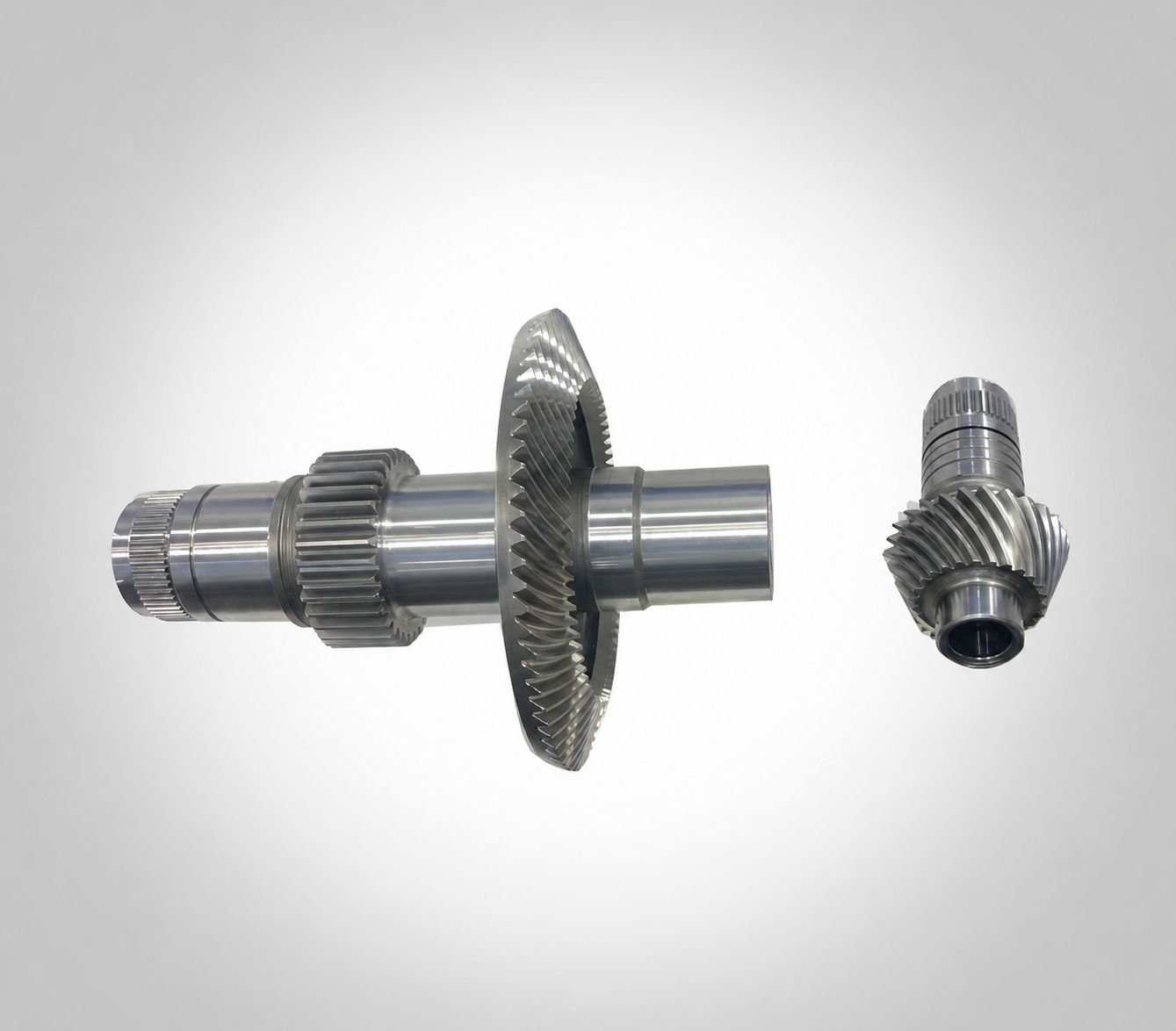
Helical Gear Materials
Highly loaded helical gears commonly use case-hardening steels such as 16MnCr5, 20MnCr5, 18CrNiMo7-6, 20CrMnTi, SAE 8620, or SAE 9310 for hard tooth flanks and a tougher core. Moderate or induction-hardened designs may use S45C/SAE 1045, SCM440, 42CrMo4, or SAE 4140. Compatible alloy or dedicated nitriding steels may be chosen where a nitrided case and lower treatment distortion suit the drawing.
Corrosion, weight, noise, and lubrication requirements can lead to stainless steel, bronze, aluminum, POM/acetal, or MC nylon in suitable lower-load or specialized designs. Stainless families can include 303, 304, or 316 for corrosion resistance and 17-4PH where greater strength is needed. Nonferrous and polymer gears have different tooth-strength, temperature, moisture, wear, and dimensional-stability limits from hardened steel.
State exact grade and standard, delivery condition, hardenability, cleanliness, mechanical properties, certification, and substitutions. Material interacts with tooth size, root and contact stress, helix-generated axial load, speed, lubricant, heat treatment, and finishing. For integral gear shafts, it must also satisfy journal, spline, thread, and core requirements; one grade should not be chosen from tooth wear alone.
Cleanliness and hardenability requirements can become important when tooth roots and cases are highly stressed. If the design calls for a restricted hardenability band, grain-size control, residual-austenite limit, or special steelmaking route, those requirements belong in the purchase specification and certificate review. They should not be inferred from a generic grade name.
Helical Gear Heat Treatment
Carburizing, induction hardening, quench and temper, and nitriding are commonly considered. Carburizing supports hard teeth with a tougher core; induction can localize hardness; through hardening changes the full section; nitriding can offer a hard case with relatively controlled distortion when alloy and case needs suit it.
Specify tooth and core hardness, case depth, test position, microstructure, decarburization, protected features, distortion, and post-treatment grinding or honing. Helix and lead are sensitive to distortion, so inspection must follow the final finishing stage. Required certificates should be included in the RFQ.
Helical Gear Tolerance
Helical-gear tolerance commonly covers profile, lead, pitch, runout, tooth thickness, helix angle, and quality grade. Bore or journal size, face runout, concentricity, shoulder position, and spline alignment influence the mounted mesh. Normal and transverse definitions must not be mixed.
Analytical gear measurement can report profile, lead, pitch, and runout. Double- or single-flank rolling, bore and face checks, coordinate measurement, roughness, hardness, and case-depth analysis may supplement it. The drawing should define governing standard, grade, datums, modifications, measurement direction, and report fields.
Backlash and contact depend on both gears and assembly center distance. Component inspection supports but does not replace system validation. Mark critical characteristics and required records; see quality inspection.
Lead modification is often used to manage load distribution under expected deflection, but its design is application-specific. Crowning, end relief, slope, or bias values must come from the released gear definition. Inspection should use the correct evaluation length and report the target trace, not only an overall grade. When noise is important, the buyer may also specify rolling-test conditions, flank form records, or matched assembly checks.
For internal helical gears, tool access, measuring reach, and datum establishment can be more restrictive than for external gears. The drawing should identify any minimum overrun, adjacent shoulders, or inaccessible inspection zones. If a functional master is required, its specification, ownership, calibration, and permitted wear must be agreed before production tooling and gauges are quoted.
Helical Gear Applications
Helical gears are common in automotive transmissions, electric drive units, industrial gearboxes, reducers, steering systems, compressors, pumps, elevators, conveyors, machine tools, and electric motors. Gradual engagement can support smoother running and higher contact ratio, but axial thrust and heat must be managed.
High-speed drives emphasize noise, lead, profile, runout, balance, lubrication, and bearing alignment. High-torque reducers emphasize case strength, root fatigue, core properties, and contact. Reversing or positioning systems may prioritize backlash and repeatability. Contamination, temperature, and duty cycle influence material and finish.
Provide speed, torque, ratio, direction, duty cycle, lubricant, mating gear, bearings, housing, environment, life target, and noise requirements with the drawing.
Axial thrust should be considered with bearing direction, housing stiffness, and shaft retention. Reversing drives may reverse thrust, while high-speed applications can make bearing preload and thermal growth more sensitive. These are system-design topics, but including the operating direction and bearing arrangement in the RFQ helps the supplier understand which shoulders, journals, and tooth flanks are functionally linked.
Helical Gear FAQ
What helical gear data is needed for quotation?
Provide module or DP, normal or transverse pressure angle, helix angle, hand, tooth count, face width, modifications, quality standard, datums, mating gear, backlash, and inspection needs.
Why does helix hand matter?
Hand determines the mating relationship and axial thrust direction. Incorrect hand or reference convention makes the pair incompatible.
Do helical gears always require grinding?
No. Hobbing and grinding requirements depend on hardness, quality, noise, geometry, access, volume, and drawing requirements. Gear shaping or other routes are evaluated only after drawing review.
What helical gear accuracy can Jinhua Machinery achieve?
Heat-treated and ground helical gears within module 4, 200 mm tip diameter, and 50 mm face width can achieve ISO 1328-1 or GB/T 10095 Grade 7 and Ra 0.8 μm tooth surfaces. Precision bores and mounting-face relationships can be combined on reviewed drawings, and other customer-specified standards can be evaluated.
Does a gear inspection report prove gearbox noise or service life?
No. A component report addresses the agreed gear and mounting features. Operating noise and life also depend on the mating gear, bearings, housing, lubricant, and duty cycle. Define separately any assembly testing and who owns system validation.
Request a manufacturing review for Helical Gears
Use the Contact form to send project requirements; send drawings as email attachments. Include material, quantity, tolerance, heat treatment, surface treatment, and application when available.