


Gear shaft manufacturing from drawings
Gear Shaft Manufacturing
Jinhua Machinery manufactures made-to-drawing gear shafts in Changshu, China for transmission and motion-control programs. Manufacturing review treats tooth geometry, shaft journals, bearing datums, bores, material, specified treatment requirements, finishing stock and inspection as one component system. Gear-to-journal runout and datum relationships are evaluated from the released drawing, together with annual volume and reporting needs. Existing technical sections retain the governing standards, verified capability ranges and drawing-review limits; this page does not claim responsibility for the wider gearbox or drive-system design.
Request a Quote
Direct answer
Gear-shaft evidence is reviewed as the relationship between tooth geometry, bearing journals, bores and shaft datums, not as separate catalogue features. Confirmed cylindrical gear and gear-shaft components can be evaluated to ISO 1328-1 or GB/T 10095 Grade 7 within the published range, subject to the governing edition, material, geometry, drawing-defined treatment, measurement method and inspection plan. Equivalent grade numbers in different standards are not assumed interchangeable.
- Technical content reviewed by
- Process Engineering and Quality Engineering
- Last reviewed
- Capability basis
- Production records and internal inspection data
What Is a Gear Shaft?
A gear shaft combines a shaft body and one or more gear-tooth sections in a single component. It supports bearings and transmits torque while the integral teeth mesh with another gear. Combining these functions can reduce joints and assembly parts, but it also links tooth accuracy to journal runout, shoulder location, spline fit, heat-treatment distortion, and the datum strategy of the whole shaft.
Gear shafts can carry spur, helical, bevel, pinion, or other tooth forms, together with splines, threads, bores, grooves, oil holes, flats, and bearing seats. Some are produced from bar; others use forged blanks for section changes or strength. The drawing must define gear data and shaft data in one coherent coordinate system.
Jinhua Machinery supports made-to-drawing gear shafts for gearbox, transmission, steering, reducer, motor, and machinery assemblies. The related gear manufacturing overview explains the wider component family.
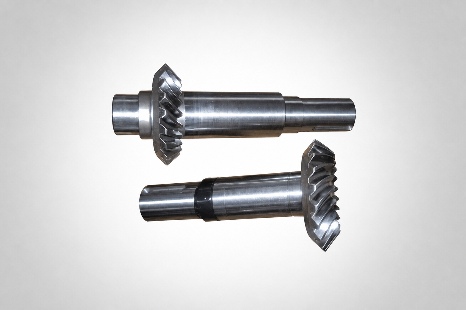
Gear Shaft Manufacturing
Manufacturing review identifies gear type, module or DP, pressure angle, helix data, tooth count, quality grade, modification, blank form, datums, bearing locations, and mating components. It also considers where the part can be held during turning and tooth generation and which surfaces require finishing after heat treatment.
Common operations include blank preparation, rough turning, drilling and milling, gear hobbing or shaping, spline cutting, thread processing, heat treatment, straightening where permitted, gear grinding or honing, cylindrical grinding, deburring, cleaning, protection, and inspection. The order is selected to control concentricity between teeth and journals and to preserve enough finishing stock after thermal distortion.
A forged blank may be appropriate for large section changes or repeated production. Bar can suit simpler geometry or flexible volumes. Dedicated cutters, fixtures, gauges, and automation can become economical as annual demand rises. Prototype and production routes should be reviewed separately if tooling or heat-treatment sequence changes.
Define the quoted delivery stage: a prepared blank, a machined gear shaft before specified treatment, or the finished part after the agreed treatment and finishing operations. Confirm whether the order includes only the integral gear shaft or also a mating gear, assembly check or functional test. Compare offers against the same controlled drawing and acceptance plan.
Separate component price from any dedicated tooling, gauges and first-article documentation. Identify the actual provider and required records for tooth generation, heat treatment, final grinding and inspection where those operations are included. Agree how changes between prototype and repeat-production routes will be reviewed before the production order is released.
Datum transfer is a major planning issue. Centers or journals used during rough turning may not remain the final functional references after teeth, splines, or bores are produced. The route should identify how the gear feature is located to the bearing axis before and after heat treatment, and how an interrupted or asymmetric feature will be supported during grinding. This review reduces the risk of meeting individual sizes while missing the assembled relationship.
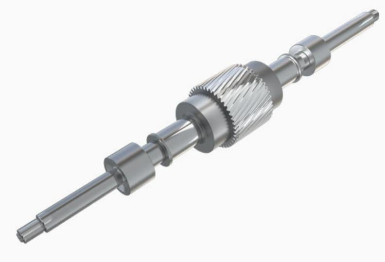
Gear Shaft Materials
Gear shafts are commonly specified in case-hardening, through-hardening, induction-hardening, nitriding, and corrosion-resistant material families. Industry case-hardening choices include 16MnCr5, 20MnCr5, 20CrMnTi, SAE 8620, 4320, and 9310 where hard teeth and a tougher core are required. Grade choice depends on section size, hardenability, case-depth target, tooth-root fatigue, core strength, and the intended finishing route.
For quenched-and-tempered or induction-hardened designs, commonly referenced grades include Chinese 45 and 40Cr, 42CrMo or SAE 4140, SCM440, and SAE 4340. Nitriding may use compatible alloy steels such as 42CrMo4/4140 or a dedicated nitriding grade when the drawing controls the compound layer, diffusion depth, and core condition. Stainless choices may include 303, 304, or 316 for corrosion-sensitive moderate-duty parts, and 410, 420, or 17-4PH where higher hardness or strength is needed.
Material grade affects blank production, tooth cutting, distortion, case response, grindability, fatigue, and cost. State the governing standard, hardenability or cleanliness requirements, delivery condition, mechanical properties, certification, and permitted equivalents. The tooth root, transitions, oil holes, splines, and bearing seats create different local demands, so any substitution requires design-owner approval.
Gear Shaft Heat Treatment
Gear-shaft specifications commonly use carburizing, induction hardening, quench and temper, or nitriding according to alloy, tooth loading, core properties, case requirement, distortion and finishing needs. These are customer-specified treatment routes, not a blanket in-house claim. Provider responsibility and required records are confirmed during quotation.
Specifications should define tooth and journal hardness, core hardness, effective case depth, test locations, microstructure, protected areas, allowable decarburization, distortion, and finishing. Grinding allowance and datum recovery after treatment require early planning. Product-specific evidence may be referenced, but every new gear shaft needs its own approved requirements and inspection method.
Selective treatment creates transitions that need clear drawing limits. A journal that remains soft, a spline that is hardened, and a ground bearing seat can each require masking, allowance, and separate verification. If straightening is allowed after treatment, the permitted method and any reinspection should be defined. Heat-treatment certificates alone do not confirm final tooth or shaft geometry.
Gear Shaft Tolerance
Gear-shaft tolerance combines tooth geometry with shaft geometry. Tooth controls can include profile, lead, pitch, runout, tooth thickness, quality grade, and contact requirements. Shaft controls can include journal size, roundness, cylindricity, concentricity, straightness, shoulder location, spline fit, thread position, and roughness. The relationship between the gear datum and bearing datums often matters more than isolated measurements.
Inspection may use analytical gear measurement, functional or spline gauges, coordinate measurement, roundness and runout equipment, diameter gauges, roughness instruments, hardness testing, and case-depth analysis. The gear standard, grade convention, datum setup, report fields, sampling, and acceptance rules must be stated. “Grade 9” or another number is incomplete without the governing standard and feature definition.
Buyers should mark safety or function-critical characteristics and request the required material, dimensional, heat-treatment, and traceability records. Jinhua Machinery inspects to the approved drawing and agreed plan; see quality inspection.
Gear measurement reports should identify the inspected flank, evaluation range, filtering or standard settings, direction of lead and profile, and the datum used for runout. Where the buyer requires a functional rolling test, contact pattern, or mating-master check, that requirement should appear on the drawing or inspection specification. Analytical results and functional results answer different questions and should not be treated as interchangeable.
Gear Shaft Applications
Gear shafts are used in automotive transmissions and steering systems, industrial gearboxes and reducers, construction machinery, electric motors, pumps, agricultural equipment, motorcycles, e-bikes, and motion-control assemblies. They can act as input, output, intermediate, sun, pinion, or actuator shafts depending on the system.
High-speed applications may emphasize noise, balance, tooth lead, runout, and bearing alignment. High-torque or reversing applications may emphasize root fatigue, case depth, core strength, transition radii, and spline interfaces. Compact mechanisms may combine several features and demand careful process access. Lubrication, contamination, corrosion, temperature, and assembly method also affect the specification.
Final gear design and application validation remain with the design owner. Include the bearing arrangement and mating-gear definition when requesting review, and state whether acceptance is for the gear shaft alone or an agreed assembled check. Start a gear shaft quotation enquiry and provide controlled drawing files by email.
Assembly and service planning can also affect seemingly minor features. Lead-in chamfers influence spline or bearing assembly, edge breaks can protect seals, oil holes must be deburred and cleaned, and identification marks must avoid fatigue-critical zones. Packaging should isolate finished teeth and journals so approved geometry is not damaged between inspection and assembly.
Gear Shaft FAQ
What gear data should be included in a gear shaft drawing?
State gear type, module or DP, pressure angle, helix data, tooth count, governing standard and grade, modifications, tooth thickness, gear-to-journal datums and mating interface. Tie the drawing revision to the material, treatment and agreed report requirements; a grade number alone is not a complete acceptance definition.
Why are gear teeth and bearing journals reviewed together?
Their runout, concentricity, axial location, and heat-treatment response affect mesh and assembly. Separate reviews can miss the datum relationship that controls performance.
Can gear shafts use forged blanks?
Yes, when geometry, load, material, volume, and tooling justify forging. The blank and machining allowances must support final tooth and journal requirements.
What combined gear and shaft precision can Jinhua Machinery achieve?
Reviewed gear shafts within the stated range can combine ISO 1328-1 or GB/T 10095 Grade 7 ground teeth with a 0.005 mm ground-journal tolerance, 0.003 mm journal roundness, and 0.010 mm tooth-to-journal runout. Precision bores can also be combined where the drawing permits. Other customer-specified standards can be evaluated.
How should gear shaft quotations be compared?
Compare the same delivery stage, tooth and journal requirements, treatment and finishing scope, and inspection package. Identify tooling and gauge costs, external-operation responsibilities, and whether mating or assembly checks are included. Do not treat a tooth report, a heat-treatment certificate and complete assembled performance validation as the same deliverable.
Related Manufacturing Cases
These are specific made-to-drawing examples. Their materials, processes and tolerances are component-specific and do not define a universal catalogue specification.


Request a quote
Request a Quote
Send drawings. Get a gear shaft manufacturing review.
Send the drawing and revision, material, critical dimensions and tolerances, surface and heat-treatment requirements, annual usage, batch volume, inspection or PPAP documents, packaging and delivery target.