


Worm Shaft Manufacturing
Jinhua Machinery manufactures drawing-based worm shafts in Changshu, China for steering, gearbox, reducer and motion-control assemblies. Each review separates the worm shaft from the mating worm wheel and evaluates starts, hand, lead, pressure angle, journals, bearing datums, material, specified treatment requirements, finishing and inspection from the released drawing. Mating-wheel data, center distance, contact or backlash requirements, quantity and reporting expectations are needed to select a route. Capability is confirmed per geometry and process boundary; this page does not represent generic worm-gear design responsibility.
Request a Quote
Direct answer
Confirmed reference capability includes heat-treated and ground worm shafts to GB/T 10089 or DIN 3974 Grade 7 within the published module, diameter and effective tooth-length range, subject to drawing review and the required measurement definition. The quotation must also establish journal datums, mating-wheel conditions, treatment-provider boundary, finishing sequence and inspection records. The stated grade is a reference condition, not a universal promise or a claim of complete worm-drive design responsibility.
- Technical content reviewed by
- Process Engineering and Quality Engineering
- Last reviewed
- Capability basis
- Production records and internal inspection data
What Is a Worm Shaft?
A worm shaft carries one or more helical worm threads that mesh with a worm wheel. The pair transfers motion between non-parallel, non-intersecting axes and can provide a high reduction ratio in a compact space. Sliding contact is greater than in many rolling gear meshes, so tooth geometry, material pairing, surface condition, lubrication, heat, and alignment are central to performance.
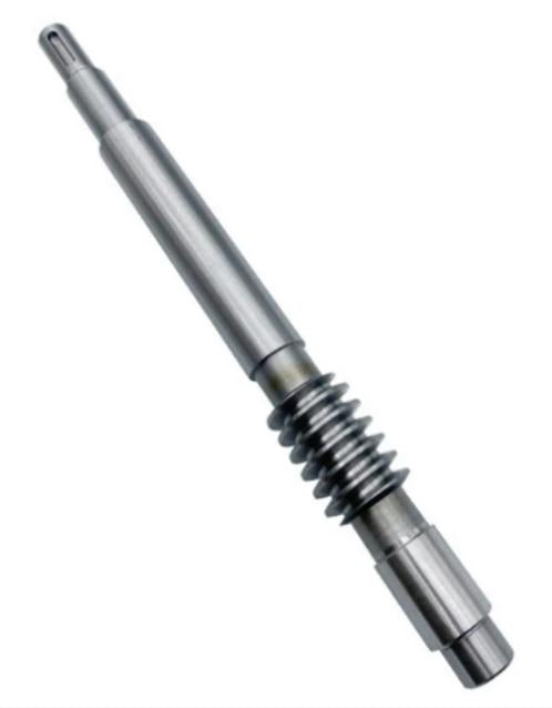
The drawing may define single- or multi-start worms, right- or left-hand lead, axial or normal module, pressure angle, reference diameter, lead angle, thread length, tooth modifications, and the mating wheel. The shaft can also contain bearing journals, shoulders, threads, splines, grooves, flats, and drive features. “Worm shaft” therefore describes a family, not a standard interchangeable item.
Jinhua Machinery reviews worm shafts from customer drawings for steering, reducer, gearbox, machinery, actuator, and motion-control applications. Design ratio, efficiency, self-locking behavior, thermal performance, and safety remain the design owner’s responsibility.
Worm Shaft Manufacturing
Review begins with the worm and mating wheel as a pair. Required data includes module or DP, number of starts, hand, lead, pressure angle, center distance, contact requirement, material pair, heat treatment, lubricant, speed, load, and datum system. The process must coordinate worm geometry with journal alignment and finishing after heat treatment.
Industry manufacturing options include turning the blank and journals, milling or whirling the worm, thread grinding for selected accuracy or hardened surfaces, and polishing or superfinishing when the drawing requires it. Additional operations can include drilling, spline or thread production, induction or case hardening, cylindrical grinding, coating, marking, and final inspection. The selected route depends on size, lead, material, hardness, quality, access, and volume.
Tools and inspection masters may be specific to the worm definition. Prototype production can use a flexible route, while repeated volume may justify dedicated cutters, fixtures, gauges, or automated checks. Allowance for thermal movement and final grinding should be planned before cutting teeth.
State whether the order covers a worm shaft only or a matched worm-and-wheel supply. Include the controlled worm drawing and the mating-wheel definition, and identify any customer-provided wheel or master used for contact checking. A worm-only order cannot establish the performance of an unspecified wheel, housing and bearing arrangement.
For quotation comparison, align the geometry convention, material pair, delivery condition and acceptance method. Identify the actual provider for worm generation, any specified grinding or treatment, and the agreed inspection records. Confirm which tooling, masters and contact checks are included instead of assuming that every listed industry route forms part of one quotation.
Cutting data must use one consistent geometry convention. Normal and axial module, lead and helix angle, and right- or left-hand definitions can be misread if a drawing combines standards or omits the reference system. Before tooling is ordered, the supplier and buyer should reconcile the drawing, calculation sheet, mating-wheel data, inspection output, and any approved master. A small definition error can produce a part that looks plausible but cannot establish the intended mesh.
Worm Shaft Materials
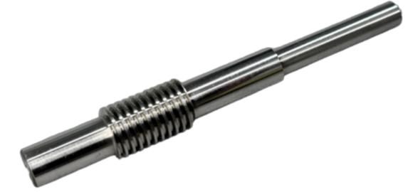
Worm shafts commonly use S45C or SAE 1045 for moderate-duty designs, and SCM440, 42CrMo4, or SAE 4140 where greater hardenability and core strength are required. Case-hardening grades such as 16MnCr5, 20MnCr5, 20CrMnTi, or SAE 8620 may be selected for a hard wear surface with a tougher core. Corrosion-sensitive designs may consider SUS303/303, 304, or 316, while 420 or 17-4PH can provide different combinations of hardness, strength, and corrosion resistance.
The mating wheel is normally selected as part of the tribological system rather than copied from the worm material. Industry wheel choices include tin or phosphor bronze such as C93200, aluminum bronze such as CAC702 or C95400, cast iron for suitable duties, and POM or MC nylon for lower-load, quieter mechanisms. Relative hardness, conformability, seizure resistance, heat dissipation, lubricant, speed, load, and temperature determine whether a pair is appropriate.
State exact grades, standards, conditions, certification, and permitted substitutions for both members. Machinability before hardening, distortion, grindability, surface finish, corrosion, contamination, and duty cycle influence the route. A generic “steel worm and bronze wheel” description is insufficient for quotation or life evaluation; material approval remains with the design owner.
When a hardened steel worm runs with a bronze or polymer wheel, the wheel material, surface finish, lubricant, and break-in assumptions are part of the system. Changing only one member can alter wear, friction, temperature, and debris behavior. Material certificates confirm identity; they do not validate the tribological pair. The equipment owner should approve the pair and the manufacturing drawing should preserve that decision.
Worm Shaft Heat Treatment
Carburizing, induction hardening, quench and temper, and nitriding are commonly considered for steel worms, depending on alloy, case requirement, core properties, distortion, and finish. A hardened worm may be ground or polished afterward to restore geometry and surface quality. Softer or through-hardened designs use different wear and strength assumptions.
The specification should state hardness, effective case depth if applicable, core properties, test locations, areas to protect, microstructure, decarburization, straightness, and post-treatment finish. Worm lead and journal alignment can move during treatment, so roughing, allowance, fixturing, straightening limits, and final inspection need one plan.
Worm Shaft Tolerance
Worm-shaft tolerance can include lead error, profile error, pitch variation, runout, thread thickness, outside and root diameters, lead angle, surface roughness, and relation to bearing journals. The mating assembly can add center-distance, backlash, contact-pattern, and axial-location requirements. Specify the governing gear standard or provide complete proprietary geometry.
Inspection methods may include analytical gear or thread measurement, lead and profile checks, measurement over wires, runout and roundness equipment, journal gauges, roughness instruments, hardness tests, and contact-pattern evaluation with the mating wheel. The report must use the same normal or axial definition as the drawing.
Bearing-seat size, straightness, shoulder position, and worm-to-journal concentricity can influence contact and noise. Buyers should define critical features, sampling, master or gauge responsibility, heat-treatment records, and traceability. Review quality inspection for the general control approach.
Contact checking should reproduce the intended assembly closely enough to be meaningful. Center distance, shaft angle, bearing support, marking compound, load, and backlash can change the observed pattern. If a master wheel or customer-supplied mate is used, ownership, calibration, wear limits, and replacement must be agreed. For serial production, the control plan should distinguish setup approval, periodic analytical checks, and routine shop-floor gauges.
Worm Shaft Applications
Worm shafts are common in compact reducers, steering systems, actuators, valve drives, lifts, conveyors, positioning equipment, packaging machinery, home appliances, and industrial motion control. They are useful where a large ratio, compact right-angle arrangement, smooth motion, or controlled back-driving behavior is desired.
Steering and actuator programs may emphasize backlash, contact, noise, corrosion protection, traceability, and repeated assembly. Industrial reducers may emphasize thermal capacity, lubricant, duty cycle, wear, and housing alignment. Positioning systems may prioritize repeatability and low backlash. The application determines whether efficiency, self-locking tendency, life, or noise is most important.
Use the worm shaft quotation enquiry to define the supply scope and application, then provide the controlled drawings and mating-wheel information by email. Performance targets, lubrication and the assembled validation method must come from the design owner; they are not inferred from the shaft outline.
Self-locking should never be assumed solely because a drive uses a worm. Lead angle, friction, surface finish, lubricant, temperature, vibration, wear, and external load all influence back-driving behavior. If holding a load is safety-related, the equipment designer must validate the condition and provide an independent braking or restraint strategy as required by the application.
Worm Shaft FAQ
What worm geometry is needed for quotation?
Provide the controlled drawing revision, module or DP and its normal or axial convention, starts, hand, lead, pressure angle, diameters, thread length and datums. Include the mating wheel, center distance and agreed contact or backlash requirements, and say whether the wheel or master is supplied with the order or by the customer.
Why must the mating worm wheel be considered?
The material pair, center distance, contact, backlash, lubrication, and alignment determine how the mesh operates. Shaft geometry alone cannot define the complete interface.
Are worm shafts always ground?
No. Milling, whirling, grinding, and finishing routes depend on material, hardness, geometry, quality, surface requirement, and volume. The drawing defines the required result.
What worm-shaft accuracy can Jinhua Machinery achieve?
Heat-treated and ground worms within module 4, 100 mm outside diameter, and 100 mm effective tooth length can achieve GB/T 10089 or DIN 3974 Grade 7 under the stated reference conditions. Ground journals and worm-to-journal runout are controlled to the reviewed drawing, and other customer-specified standards can be evaluated.
What should be agreed before accepting a worm shaft order?
Agree whether acceptance is for the shaft alone or a defined worm-and-wheel check, which drawings and geometry conventions govern, and who supplies the mating wheel or calibrated master. Specify inspection records and the actual process providers. Component inspection does not validate efficiency, thermal behavior, life or self-locking of the assembled drive.
Send drawings. Get a worm shaft manufacturing review.
Send the drawing and revision, material, critical dimensions and tolerances, surface and heat-treatment requirements, annual usage, batch volume, inspection or PPAP documents, packaging and delivery target.